Transvac’s range of Instantaneous Jet Heaters provide a simple, low cost, silent and reliable method of heating a liquid inline using Steam Ejector technology. Our experience in designing and manufacturing Jet Heaters spans over 45 years, making us a world leader in steam heating.
By bringing the steam into direct contact with the cold liquid, both the sensible and latent heat of the steam is fully dissipated within the liquid, making the Transvac Instantaneous Jet Heaters very efficient. Transvac Heaters are also designed to perform this operation silently to prevent undue noise and wear normally associated with steam ‘collapse’.
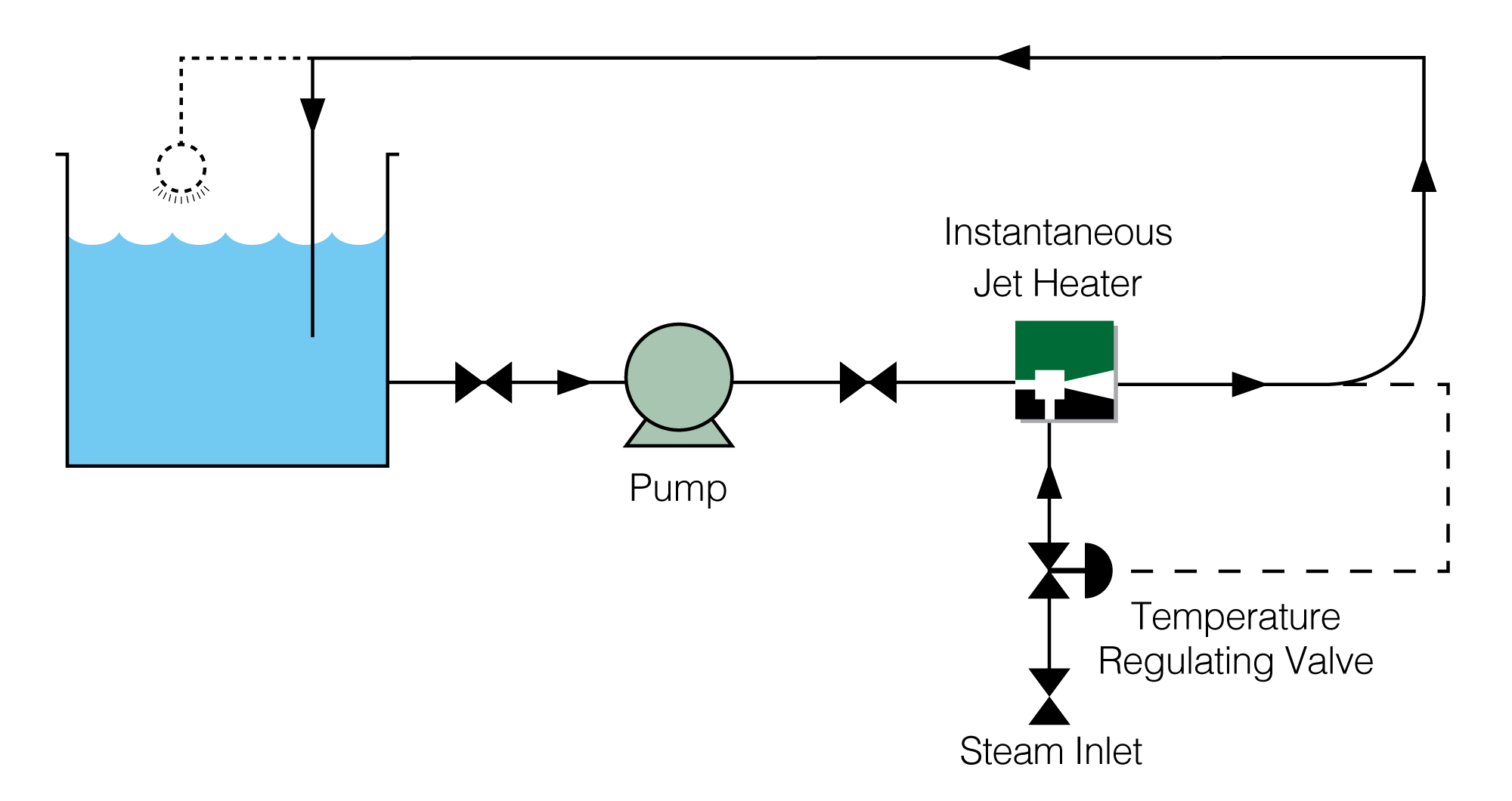
In simple terms, Instantaneous Jet Heaters (IJH) use steam to heat a liquid stream.
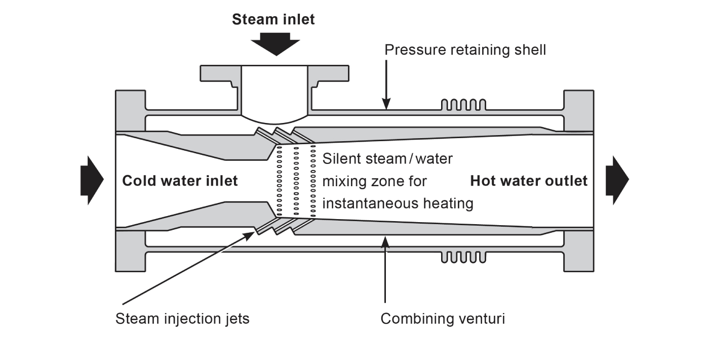
Pressurised cold liquid is introduced to the IJH and is immediately accelerated through the combining nozzle, resulting in a local pressure drop.
Pressurised steam enters the IJH and is discharged into the liquid at high velocity, via a number of jets around the combining tube. This method of combining steam and liquid prevents ‘backing up’ should the steam be under a much higher pressure than the liquid.
Both the sensible and latent heat of the steam is fully dissipated within the liquid, making Transvac’s instantaneous jet heaters very efficient.
Our IJH’s are also designed to combine the two streams, silently and instantaneously to prevent undue noise and wear normally associated with steam ‘collapse’.
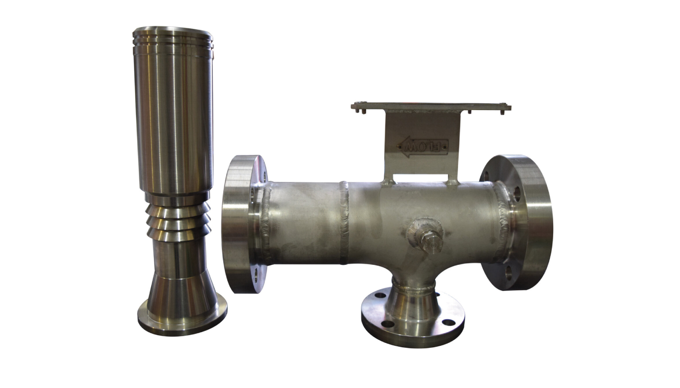
Size 3 Inline Instantaneous Jet Heater, shown with internals removed.
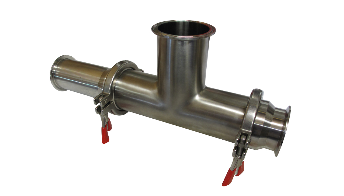
Size 3 Instantaneous Jet Heater with Tri-Clamp Connections (Hygienic Design)
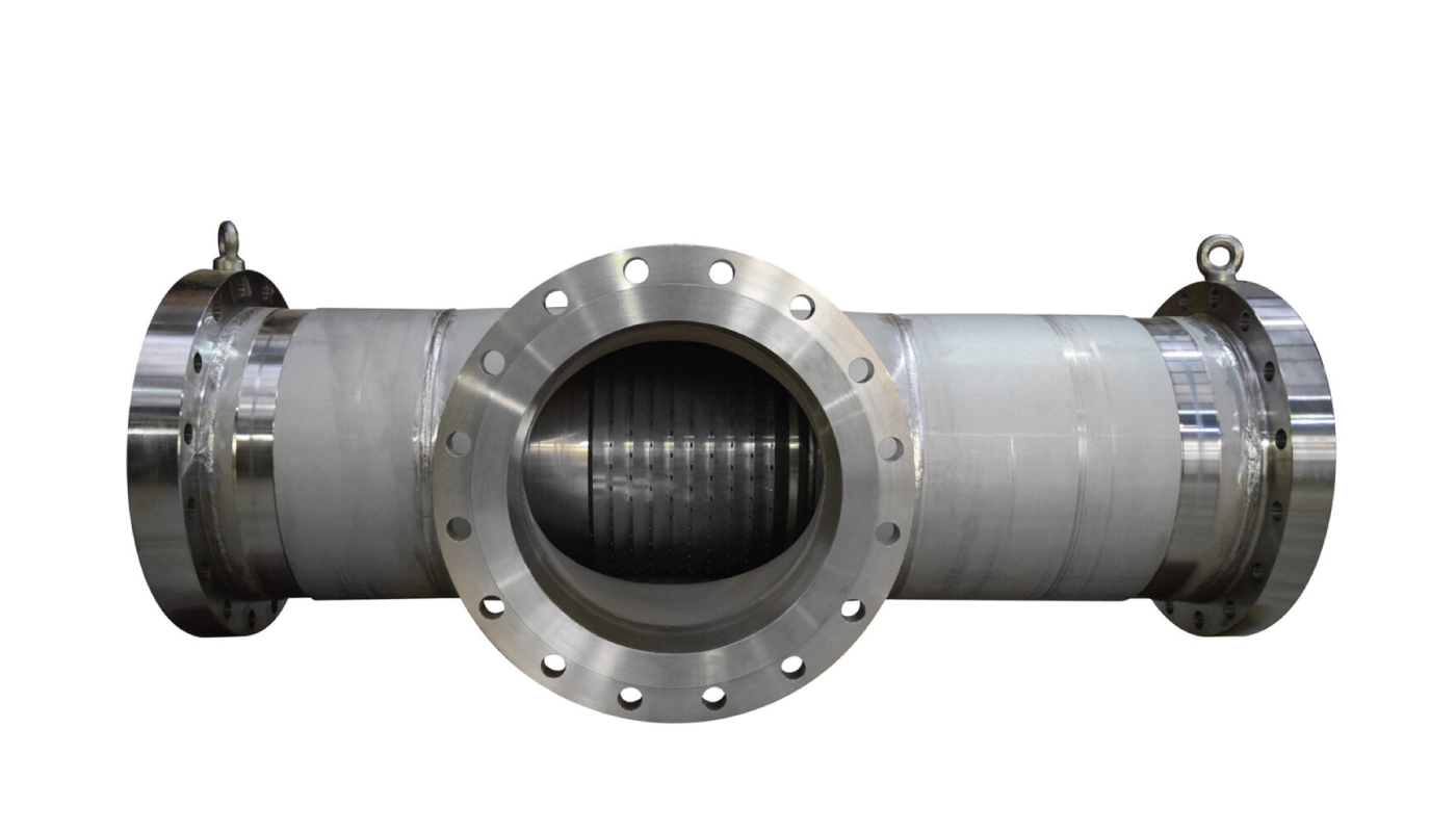
Size 18 Instantaneous Jet Heater
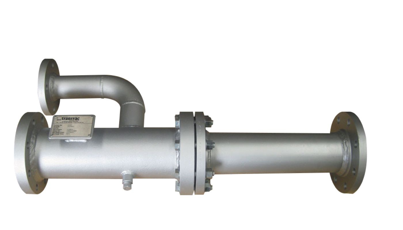
Size 4 Instantaneous Jet Heater with Steam inlet branch
All Instantaneous Jet Heaters are custom designed to suit each application with either single units or complete systems available. Proprietary and recognised codes of practice are used including ASME, PD5500 etc. Designs comply with the latest European standards and units are CE marked where applicable. Typical materials of construction include carbon steel, stainless steel, Hastelloy etc. Connections include flanged, screwed or hygienic.

Food and Pharmaceutical manufacturers often spray acid and alkali solutions into process tanks as part of their CIP cleaning systems. Traditionally these CIP systems have used metering pumps for Chemical Dosing. These pumps dose chemicals into demineralised water and indirect contact Heat Exchangers to raise the solution temperature.
Using a Transvac Combined Heating and Chemical Dosing System this process can be performed efficiently and almost silently in one simple package. The first part of the system incorporates a Transvac Steam Jet Heater that heats pressurised demineralised water to the desired outlet temperature.
The second part of the system incorporates a Transvac Liquid Jet Pump that entrains and mixes chemicals with the demineralised water and discharges the solution to the spray cleaning ball.
In operation a Jet Heater injects hygienic steam at high velocity into the cool water raising its temperature almost instantaneously to the desired temperature. Transvac Heaters are custom designed to suit the process conditions and perform the heating operation silently.
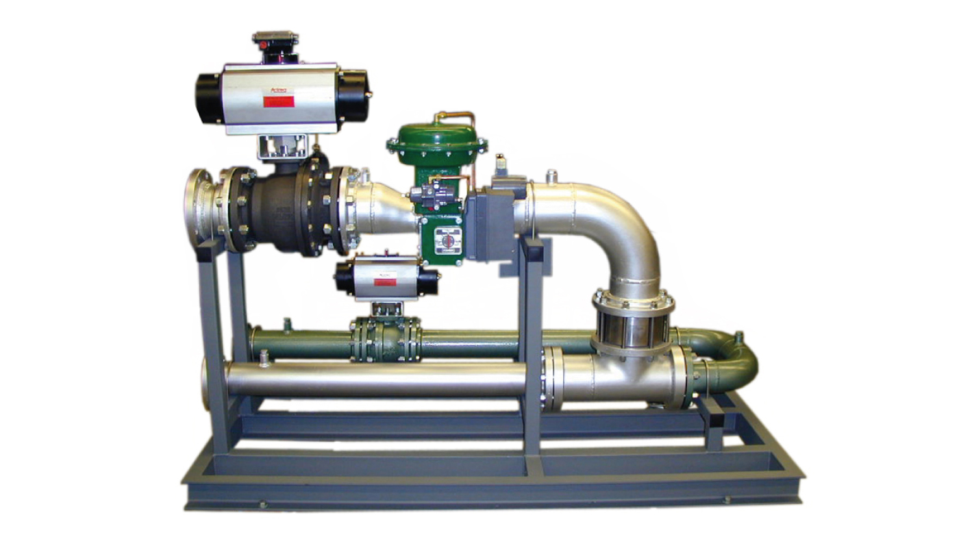
Hot Water Heating System for a Chemical Works
The fluid to be heated is usually water; however when the liquid is not water the density and heat capacity of the fluid must be known.
For most systems a 0.5 bar drop is considered reasonable; however the minimum pressure drop of 0.3 bar can be achieved. The pressure drop selected only occurs when no steam is flowing (on start-up or when no heating is required).
During normal operation, the pressure drop is less as the steam gives the liquid a slight pressure ‘boost’.
In general, the maximum temperature you can heat to is 5 – 0 ºC below the saturation temperature of the liquid. When the liquid is heated beyond this temperature flashing can occur which can cause the unit to vibrate and become noisy.
However, if you want to calculate the maximum temperature, it can be calculated by the following method:
Saturation temperature = Steam pressure in the mixing zone x 0.85. For example, if an IJH has a liquid-side inlet pressure of 2.5 bar g and the pressure drop is 0.5 bar, the pressure in the mixing zone is 2 bar g or 3.013 bar a.
When designing a unit, the steam pressure at the inlet flange of the IJH must be adequate to overcome the liquid pressure.
If the steam pressure becomes lower than the liquid pressure the liquid could enter the steam line causing vibration. It is therefore important to consider the pressure drop across valves and equipment upstream of the IJH to ensure that the correct pressure at the steam inlet flange is maintained.
The fluid to be heated is usually water; however when the liquid is not water the density and heat capacity of the fluid must be known.
The recommended straight length distance downstream of the IJH before any bends, sensors or equipment is 6 – 0 pipe diameters. Please reference the typical application on page 2 which illustrates these recommended distances.
The pipework should always match the connection size of the unit. However if the pipework is a greater NB than the unit the pipework after the discharge flange should be a minimum of 6 – 0 pipe diameters length before returning to the pipework NB.
The IJH can be installed and operated in almost any position but, the preferred orientation is to have the liquid flow horizontal with the steam branch on the top of the unit to help with drainage. However, we do not recommend that the unit be installed vertically with the flow downwards.
The IJH can be supplied with any type of connections on termination or body from flanged, screwed, sanitary clamp connections.
If the steam supply is known to be wet or contains less than 5 ºC of superheat, we strongly recommend the use of steam traps and separators in the pipeline. If the condensate is inadequately removed, the internals of the IJH will be subjected to conditions which will increase the wear rate, eventually resulting inefficient operation.
We strongly recommend the incorporation of strainers in both the steam pipeline and cold liquid pipeline. The strainer in the steam pipeline should be positioned upstream of any control valve and, the strainer in the liquid pipeline should be positioned upstream of the unit but, no closer than 6 pipe diameters from the liquid inlet flange.
Providing the steam used for heating is dry and saturated (or slightly superheated) an IJH needs little maintenance and should provide many years of service.
If, however, the liquid being heated is corrosive or abrasive, the steam is ‘wet’ or the unit is located within a harsh environment, the unit may need additional inspection. If it is determined that the IJH ‘body’ is in good condition but the internals are worn, you would need to evaluate its replacement or scope in its eventual replacement into the maintenance programme.
Notifications