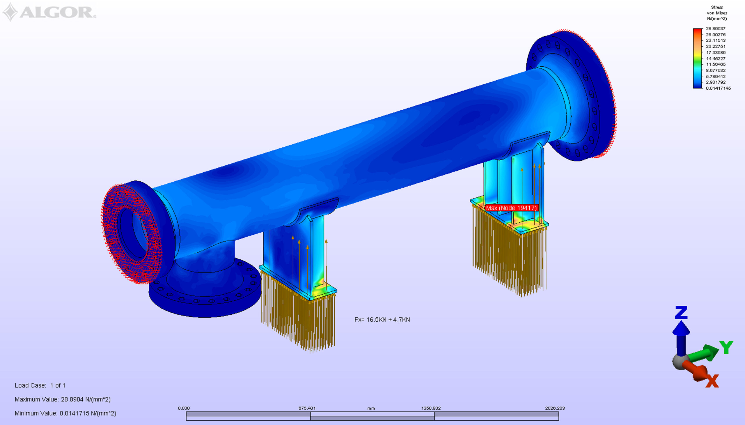
Nozzle Loads
Because of the general construction of Transvac Ejectors, it is impractical to apply direct nozzle loads and applied bending moments using recognised techniques such as WRC 107/297 and/or PD5500 Appendix G, for example. This is because such techniques are only applicable to cylindrical nozzles radially attached to constrained cylindrical vessels, within certain geometry limitations.
However, Transvac range of Ejectors are more similar to piping items than vessels because they are not designed to store fluids, they are not usually constrained and finally, often have nozzle to shell size ratios which lie outside the geometry permitted in the above techniques.
Further, if the Transvac Ejectors was analysed as vessels, then when calculating for nozzle loads, we would have to assume certain boundary conditions, which may prove unrealistic when the items are eventually considered as an integral part of the overall piping system.
Although Transvac Ejectors can sometimes be regarded as pressure vessels when designing for a pressure load, they are usually considered as piping components when designing for external nozzle loads and moments.
Practice has shown that the most acceptable and expedient approach is for clients to consider Transvac Ejectors as an integral part of the piping system when performing their piping stress analysis. This would be carried out using drawings supplied by Transvac. This approach allows clients to treat Ejectors as integral components of the piping system at an early stage of the project, thereby avoiding possible costly changes at a later date.
Transvac Ejectors are mechanically designed in accordance with the Piping Standard ASME B31.3, client Piping Specifications and relevant client (Aramco) specifications. Ejectors are as simple to install as piping items and do not require any special commissioning requirements.


